Make Your Own Infrared Security System Using a Simple Webcam

There may have been times when you wanted to have your own infrared security system to monitor the perimeter of your house. The problem is that night vision cameras and illuminators can cause a huge dent in your pocket and so you decided to put your plans on the back burner. Well, you may want to bring that plan back to life again because there is an inexpensive way to have your own home made security system.

Soldering Gun

You just need a simple webcam, preferably the cheap ones. You would also need some used film negatives, a couple of high intensity infrared LEDs which you can get from any electronics store for less than a dollar, a power device for your LED lights which you can get for less than ten dollars, some cardboard, polarity wires, an electronic bread board, and tools like a soldering gun.

Soldering Gun

First, you have to open the webcam by unscrewing its plastic casing. Then try to remove the webcam's lens assembly from the holder. On some cameras, this is screwed on the assembly, while on other cameras, it just kind of snaps into place.

Once you have taken off the lens, you should see a small square shaped glass stuck at the bottom. That would be the red-tinted infrared filter of the webcam, the one that stops IR light from being captured by the webcam's sensor. Remove this filter carefully with a penknife by slowly scratching the glue off its edges and then levering it out with the same knife.

Replace the IR filter with a used negative, preferably the blackest that you can find, and cut it to two pieces of approximately the same size of the IR filter you took out. Fit these two pieces of cut film into the slot where the IR filter used to be. Carefully affix your new filter with quick drying glue, taking care not to spill some of the glue onto the webcam's lens or on the 2 pieces of negatives.

Put the lens back on the webcam and reassemble the rest of the parts. Then, connect the camera to your computer and see if it can still detect any color. Next, try to put eight high intensity infrared LEDs on a bread-board and connect it using a series-wiring configuration. Make sure the polarity of each LED corresponds to the other and then have it insulated by a thin electrical tape. Attach this assembly to a strong cardboard and connect it to a power supply.

Try to focus your reconfigured webcam to the lights to see if it is powered on. If everything works according to plan, attach these two assemblies on another cardboard by putting the camera on top and the illuminator at the bottom.

Now, you have a working assembly of a near infrared security camera with an illuminator. The best thing about this is it will cost only about forty to fifty dollars. How is that for half an hour's task?

Make Your Own Infrared Security System Using a Simple Webcam
Soldering Gun

Android Tablet Device Portable Digital Media Player 9 Inch Tv Monitor

Do it Yourself Solar System - Solar Power Made Easy, and Much Cheaper Too!

Ever looked into purchasing a solar power system for your home? Ever searched the internet for those "do it yourself solar system" kits, just to find a solar dealer that put together a package that costs about ,000, ships you the materials, and you are on your own?

Soldering Gun

That is a daunting task even for the most handy of do it yoursefer's, as you do not receive any type plan or considerations to build such a system, let alone be cost effective.

Soldering Gun

There are definitely some things to consider from a do it yourself standpoint before considering installing a do it yourself solar system.

Are you willing to climb on your roof to install solar panels? Spending time on your roof is part of the process of building a solar power system. The hardest part is actually getting up there. Once you can get over that, the installation of the solar panel is a breeze. It is as simple as connecting the brackets to a support beam in the roof, and connecting the solar panels to the brackets.

Do you have an open view to the south on your roof for maximum solar exposure? In order for photovoltaic cells to produce the most electricity for your home, they must face the southern sky. If you have large trees blocking the way, then alternatives can be considered, such as building a solar stand that has an unobstructed view of the southern sky for maximum exposure.

Are you willing to save money by building your own solar panels? This is a no-brainer, as the cost of building a solar panel can be done for about 0, if you shop around properly, and purchase bulk lots of solar cells off of the internet. I once found a bulk lot of 72 solar cells for about . That's more than enough solar cells to start your do it yourself solar system, and this price pales in comparison to the hundreds, even thousands of dollars a manufactured panel costs.
Can you follow step by step directions and videos?

If you answered yes to the above questions, then you are well on your way to building your own solar power system for your home.

There are many do it yourself solar system designs on the market today, all of which are designed to take the guesswork out of building solar panels, installing the solar panels, and wiring the solar panel systems into your home for a fraction of the cost of purchasing ready-made solar panels, and having someone come to your home to install them.

I made my first attempt at building a solar panel, and it was much easier than I anticipated. Once I ordered my materials (the solar cells) and picked up a little bit of parts from my local hardware store, the construction was very simple. First I measured the size and arrangement of the solar cells. From there, I got my dimensions to build the frame to mount the solar cells. Next the frame was actually constructed. The next step, which was the toughest (and at the same time, was still easy), was soldering the solar cells together. This was about as tricky as using a hot glue gun and making a relatively straight line. Once I got the solar cells all pieced together, I added them to the frame and secured them. After that, the solar cells were wired together, and the cover to the frame was added. Voila! A solar panel. I tested it, and it was generating the necessary wattage (18 volts) and was working fine.

All of this took me about 6 hours to do, since it was my first one, and a cost of about 0. This definitely did not take very long, and once the solar cell is connected into my house wiring, it will take maybe two months of generating electricity for the solar panel to pay for itself. Not too bad!

I was shocked, but I realized that a do it yourself solar system is definitely within anyone's reach, as I am not the most "handyman" of people to begin with. I'll soon be building my second solar panel to add to my do it yourself solar system, and be on my way to making a huge dent in my electric bill.

Do it Yourself Solar System - Solar Power Made Easy, and Much Cheaper Too!
Soldering Gun

Mclane Reel Mowers 3D Home Theater

Is Your Headphone Jack Plug Giving You Problems?

You are doing your favorite activity and listening to music on your headphones. Suddenly the music just stops or its interrupted with a loud crackle. How annoying! Weather it is your old Sony Walkman, MP3 player, new Apple iPod, iPhone, iPad or your lovely laptop, the thought of an audio malfunction could be shocking. Most likely your audio interruption is caused by a problem with your Headphone Jack Plug.

Soldering Gun

Sometimes it's the simple things that count. With all the complicated circuitry and programs going on inside today's audio capable gadgets, it may be the common headphone jack that causes the most problems. A set of headphones and the headphone jack gives us the capability auditory interaction with today's popular electronic devices. Depending on the type, a headphone jack costs anywhere from a fraction of a dollar to a few dollars. That is why it can be very frustrating when you realize you may have paid hundreds of dollars for an electro-gadget that doesn't work because of a relatively cheap!

Soldering Gun

The term headphone jack or headphone plug refers to both male and female metal connectors that come in various sizes. The most common sizes are a 6.35mm or 1/4" jack, 3.5mm miniature jack and a 2.5mm sub-miniature jack. The malfunction of a simple headphone jack can be a big headache.

There are a few different causes for its malfunction. The female part of a headphone jack is most prone to causing a failure because it us an opening into the inner circuitry of any device that has one. Allowing sand, dust or water to get inside could cause a problem. Some of today's latest audio devices have a "moisture" detection sensor. If liquid or excessive moisture gets inside the headphone jack, a small LED light will change from white to red to indicate unacceptable moisture levels. Such indication may cause the device to shut down in an attempt to avoid further damage. Another common cause of headphone jack failure is a bad connection do to the spreading of the internal metal contacts. This is the reason for most repair requests or returns for MP3s, cell phones and iPods. It has been noted as one of the most discouraging problems for audio technicians. Technicians have stated that it is a shame that such beautifully designed devices fail because of a jack malfunction.

So, what can be done to avoid and/or repair a problem with headphone jacks? If you think dirt or dust got into the jack, you could try blowing out the jack hole. You can blow into the hole yourself or buy a can of compressed air commonly sold in electronic and computer stores that are made specifically for cleaning electronic devices. If you think liquid or moisture got into the hole, just let it sit for a while in a dry warm place for a couple of days, the device might dry out and begin working properly. If none of these works and your device is under warranty, send it back to the manufacturer for repair.

Although not recommended, you could try a do it yourself fix. To do this, remove the cover of your device. This may require you to remove a number of screws around the perimeter of the cover. If you have soldering skills you can remove the old solder from the jack by heating up the old solder with a soldering gun and tabbing it off with a toothpick. Then apply new solder using proper soldering technique. If you do not know how to solder try cleaning jack connectors with an alcohol swab. Test your device to see if it works. If not, you may want to re-solder the connections. Soldering properly requires some skill.

If all of the above methods do not resolve your jack problem, your best bet may be to send it back to the manufacturer for a repair. Follow the instructions in your user manual for the repair process. But there are ways to avoid problems with your headphone jacks. Be gentle when inserting the male jack into the female receptor. Angling when injecting may cause the female connectors to spread, thus causing a loose connection, which may require constant jiggling. Use device clips to secure your device to your belt or pocket to avoid pulling on the jack if your device falls or is pulled.

Sometimes the best way to avoid jack damage is prevention. Some devices come with jack covers but others do not. If you have a device that does not have a headphone jack cover you can buy one at your electronics store or go on-line and search for "headphone jack cover". Protect your investment, avoid dust and moisture and get a cover if you don't have one.

Is Your Headphone Jack Plug Giving You Problems?
Soldering Gun

Black Friday 100W 5pc Soldering Gun KiT: Cutter:Flux:Solder:Case 2011 Deals

Nov 19, 2011 03:38:33

Black Friday 100W 5pc Soldering Gun KiT: Cutter:Flux:Solder:Case Deals
Click for larger image and other views

100W 5pc Soldering Gun KiT: Cutter:Flux:Solder:Case

>> Click here to update Black Friday prices for 100W 5pc Soldering Gun KiT: Cutter:Flux:Solder:Case <<


Black Friday 100W 5pc Soldering Gun KiT: Cutter:Flux:Solder:Case Overview

Brand New 100 Watt Soldering Gun Kit 110 Volts / 60 HZ Power: 100 Watts 2 Extra Cutters Container of Flux Tube of Solder/Wire Gun has light bulb for easy viewing during solder Includes a Blow Mold Carry Case


SAVE NOW on Black Friday offers below!

Available In Stock.

This Black Friday 100W 5pc Soldering Gun KiT: Cutter:Flux:Solder:Case ships for FREE with Super Saver Shipping.

Price : Click to Check Update Prices Please.

100W 5pc Soldering Gun KiT: Cutter:Flux:Solder:Case

Limited Offer Today!! 100W 5pc Soldering Gun KiT: Cutter:Flux:Solder:Case Black Friday and Cyber Monday 2011 Deals

Projector Short Throw Supplements For Muscle Growth Digital Pen

How to Build an Economical Speaker Box

Speaker boxes are used to house several component subwoofers and other speakers in an enclosure. Although most subwoofers are sold separately, you might want to put them into one box or enclosure hence the use of a speaker box. Speaker boxes are not hard to build but are very challenging for if done correctly they can help enhance the output of stereo source. For those who are not so good with craftwork can certainly order the sub woofers already pre-enclosed.

Soldering Gun

What is needed in order to build a speaker box?

Soldering Gun

It all depends on your budget and intent of the speaker boxes. You have to determine the size and the materials used. The best material that you can use is a ¾ inch medium density filter board. If you have the cash to spare, you can opt for more exotic materials but most people use fiberboard.

Aside from the fiberboard, you will also need: a jigsaw (a bladed cutting power tool), a power drill, a spiral but, a ¾-inch bit, a router, sand paper, spray glue, solder gun and ammo, and some carpet if you want to cover the speaker box.

Most subwoofers on the market come with a set of optional instructions that let you design an enclosure for it. No need to figure out the dimensions when a set of measurements have already been included in the package. In this case it means that you won't have to go through trial and error designing an enclosure since it has the common specs for most speaker boxes.

One important thing you have to realize is that if the measurements are given on an interior measurement, you might have to adjust the measurements by as much as ¾-inch.

It is also ideal to trace your desired design and size measurements on the filter board rather than doing any freehand cutting. Avoid using markers for they can be unsightly if the speaker boxes are not covered with carpet.

For obvious reasons, you have to use your jigsaw to cut the design and not a knife or other cutting tool. The jigsaw lets you curt clean and neat. Once the pieces have been cut out, it is a good idea to make a trace of where the speakers would go into. In order for you to do this you would have to use a router. Once you have used the router to cut the holes, you would have to use sand paper to smoothen the holes made.

You should also look into creating holes so that the necessary cables can pass through. If the template or instructions do not have any notes for holes, it is best to create 2 inch holes on either side of the speaker box. Always sand them through so that there are no snags when done.

After the holes have been cut, you can now assemble the boards together. Using screws, nuts and washers, you have to make sure that they fit tight and don't rattle. Always leave the front of the box last so that any last minute works can be dealt with.

The next part is the easiest for all you have to do is out the subwoofers in, close the front panel, and plug the power and connectors in.

The real workload is in the construction of the speaker box and that being said, you have to make sure that the work done is up to precise and exact.

How to Build an Economical Speaker Box
Soldering Gun

European Baby Strollers Panasonic Stereo Systems Bernzomatic Micro Torch

Installing a Killswitch

The killswitch is possibly one of the biggest fads in recent guitar history. Ever since Buckethead's "Jordan" appeared in Guitar Hero II, guitarists everywhere have latched on to this simple, yet amazing modification. However, many people have no idea what a killswitch is, let alone how to install one onto a guitar.
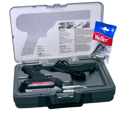
Soldering Gun

What is a killswitch, and how does it work?

Soldering Gun

Really, the name tells you the basics of the modification. A killswitch is a "switch" that "kills" the sound. When you put the switch in one position, the guitar is silent, while in another position, the guitar makes sound. Simple enough, right? Not quite...

Many amateur electricians will try to wire the killswitch in such a way as to "cut" the signal. In a perfect world, that would work. You could simply disconnect the wires, and there would be silence. Unfortunately, our world is far from perfection, so doing that will give you more problems than it's worth. Instead, the signal needs to be grounded, which will produce the same basic effect, without the undesired consequences.

What materials do I need?

1. A switch of your choosing. This can be a headache on its own. For the inexperienced, picking out of the thousands of switches available at their nearest Radioshack can be tedious, to say the least. Preferably, go for a SPST Normally Open (N.O.). If you are looking for a Buckethead-style killswitch, look for a momentary push-button. If Tom Morello is closer to your style, pick up a standard toggle switch.

2. Wire. I used speaker wire, but any insulated wiring should do fine.

3. Soldering iron. Obviously, since we are installing electrical components in a guitar, we are going to need the ability to solder. Any soldering iron will do, though for safety concerns, I prefer a soldering gun.

4. A drill, and the proper bit size. This varies, depending on the size of switch you buy. Just remember, you can always increase the size of the hole, but never decrease it.

Installing the Killswitch

Start off by drilling your hole in the pickguard. Basically, just use common sense here. Make sure you're using the right size drill bit, make sure you have room in that spot for your switch, etc. Once you have the hole drilled, go ahead and put the killswitch into place. With the killswitch in place, go ahead and start heating up your soldering iron. Before we actually start soldering, however, I want to show you two pictures, because they illustrate what to do and what NOT to do.

The first picture: what to do with a N.O. (normally open) switch. As far as electronics are concerned, when two points are connected, they become the same point. Therefore, when you look at this diagram, you noticed that when the switch is activated, the hot (red) wire becomes grounded (green), thus silencing the guitar. This is by far the safest and most effective way to wire a killswitch. Unfortunately, the website also demonstrates a method you should NEVER use to wire a killswitch, or anything at all, for that matter.

Usually, we try not to bash other websites, but when something is blatantly wrong and/or dangerous, something has to be said about it. This diagram supposedly shows how you are supposed to wire a killswitch using a N.C. (normally closed) switch. From a practical, guitarist standpoint, using this wiring would not silence your guitar; it would do the exact opposite. Hitting this switch the way it is set would cause an obnoxious hum, one that even shielding your guitar could not fix, to come out of your amplifier, similar to unplugging your guitar and touching it to a piece of metal. On top of that, disconnecting the ground is the last thing you ever want to do with electronics. Why, you ask? Electricity always looks for the path of least resistance to the ground. If it is cut off from the intended ground, you become a potential target, thus increasing the risk for electrical shock. If you insist on using a N.C. switch, you would want to cut the power wire, but even that will give less than desirable results. Your best bet is to use the first diagram, using a N.O. switch. Even with this, however, there is one issue...

HELP! My killswitch pops!

Most tutorials don't teach you how to fix this mod's unfortunate side effect - the killswitch pops each time you press it. There are two ways to remedy the situation. The first way is the easiest: turn up the distortion. With enough distortion, the popping will be drowned out. However, this is just a band-aid for the real problem: the wiring. Rumor has it that putting a high-value resistor (greater than 2M) between the lugs on the switch will stop the popping, though I have yet to get my hands on such a resistor, and have yet to hear a definitive answer on the subject. However, as soon as I try it out, I will post it here.

Do you have other suggestions for our killswitch enthusiasts? Be sure to leave us a comment!

Installing a Killswitch
Soldering Gun

Black Friday Weller D650 Industrial Soldering Gun 2011 Deals

Nov 17, 2011 02:54:16

Black Friday Weller D650 Industrial Soldering Gun Deals
Click for larger image and other views

Weller D650 Industrial Soldering Gun

>> Click here to update Black Friday prices for Weller D650 Industrial Soldering Gun <<

Black Friday Weller D650 Industrial Soldering Gun Feature

  • Dual-heat gun produces 300 or 200-Watt
  • Nickel-plated copper secondary, heat resistant-thermoplastic housing
  • Heavy duty grounded cord
  • 2-Wire cord.
  • UL and cull listed.


Black Friday Weller D650 Industrial Soldering Gun Overview

650

Industrial Duty Soldering Gun
  • 300/200 Watt
  • Nickel-Plated Copper Tip


SAVE NOW on Black Friday offers below!

Available In Stock.

This Black Friday Weller D650 Industrial Soldering Gun ships for FREE with Super Saver Shipping.

Price : Click to Check Update Prices Please.

Weller D650 Industrial Soldering Gun

Limited Offer Today!! Weller D650 Industrial Soldering Gun Black Friday and Cyber Monday 2011 Deals

Digital Kitchen Scale Mini Led Projector Hdmi Cable 1080I

Xbox 360 3 Red Light Flashing Light Fixes You Can Easily Do

Introduction

Soldering Gun

This article will deal with how to fix the most common reason for the xbox 360 3 red flashing lights sometimes known as the "Red Ring Of Death".

Soldering Gun

The major reason for the xbox 360 red ring of death, sometimes known as RROD, is due to faulty manufacture of the main circuit board. This faulty manufacture results in poor solder joints which connect the main electronic chips to the circuit board. As the xbox 360 heats up the circuit board undergoes minute flexing and the faulty solder joints result in loss of electrical contact for the main electronic chips with the main circuit board and results in the xbox 3 red flashing lights.

The Towel Method

This is the oldest and perhaps best known of the xbox 360 3 red flashing lights do it at home fixes. Essentially the Xbox 360 is powered on whilst wrapped in a towel for a little while. The idea is that the heat generated by the xbox melts the solder and effectively eliminates bad solder problems. That at least is the theory. the reality is somewhat different. The XBox 360 is fitted with an electronic temperature regulator which switches off the Xbox before too much damage is done. So this method has been reported to work with some units but most will switch off without resolving the issue.

The Self Heating Method

This method requires that the XBox 360 is opened and the electronic thermal cut-off is disabled. The xbox 360 is then powered on for several minutes and the CPU and GPU heat up and eventually melt the solder which then reforms and repairs the faulty connectors. I like to think of this method as the xbox 360 3 red flashing lights self healing method. To see a step by step video of this process click on this link [http://www.xboxflashingredlights.docsabout.com].

The Heat Gun Method

If you have access to a heat gun then this can be employed to fix most xbox 360 3 red flashing lights problems that require re flowing the solder to fix bad connections. Using the xbox error code to determine the location of the fault. The heat gun is directed at the xbox motherboard area in question until the solder is observed to flow and the xbox then allowed to cool.

Xbox 360 3 Red Light Flashing Light Fixes You Can Easily Do
Soldering Gun

Black Friday Weller P2KC Professional Self-igniting Cordless Butane Soldering Iron Kit 2011 Deals

Nov 16, 2011 01:23:42

Black Friday Weller P2KC Professional Self-igniting Cordless Butane Soldering Iron Kit Deals
Click for larger image and other views

Weller P2KC Professional Self-igniting Cordless Butane Soldering Iron Kit

>> Click here to update Black Friday prices for Weller P2KC Professional Self-igniting Cordless Butane Soldering Iron Kit <<

Black Friday Weller P2KC Professional Self-igniting Cordless Butane Soldering Iron Kit Feature

  • Tips and accessories screw on easily
  • Includes complete kit
  • Soldering tips are iron plated for long life
  • Gas capacity allows up to 1 hour of continuous use
  • Automatic cut-off switch when cap is inserted


Black Friday Weller P2KC Professional Self-igniting Cordless Butane Soldering Iron Kit Overview

The new Portasol® cordless soldering tool from Weller® gives you the ultimate in portable power and convenience for all your soldering jobs. Slide the fuel button forward, press the piezo switch, and the tool's super-fast heat-up lets you melt solder in under a minute. The Portasol® cordless soldering tool is powerful too, adjusting from the equivalent of 25 to 75 watts for temperatures up to 850°F. Refueled with standard butane in just 20 seconds, the Portasol® P2C lasts for up to an hour of continuous use. Kit includes tool with five tips (PPT6 3/32" double flat soldering tip, PPT12 flame tip, PPT10 hot knife tip, PPT9 hot air tip, and PPT11 hot air deflector tip), sponge and tray, tool holder, storage case, and instructions. Mfg. #P2KC. Replacement tips available.


SAVE NOW on Black Friday offers below!

Available In Stock.

This Black Friday Weller P2KC Professional Self-igniting Cordless Butane Soldering Iron Kit ships for FREE with Super Saver Shipping.

Price : Click to Check Update Prices Please.

Weller P2KC Professional Self-igniting Cordless Butane Soldering Iron Kit

Limited Offer Today!! Weller P2KC Professional Self-igniting Cordless Butane Soldering Iron Kit Black Friday and Cyber Monday 2011 Deals

Powerlite Home Cinema Figures Playsets Lcd Car Headrest

Building Your Own Still - The Perfect Science Fair Project

If you are one who is searching for that perfect undertaking that will surely win the year's award for the best science fair project then don't look any further beyond constructing the simple still. For those who do not have any idea as to what a still is, it is an apparatus that is meant to distill, or separate, liquid mixtures by boiling since different liquids have different boiling points.

Soldering Gun

Before starting with the construction, it is important to note that building a still may lead one to run-ins with the law which makes it important for one to be knowledgeable of the regulations in one's area and to devote the project entirely for scientific and educational purposes.

Soldering Gun

To start the construction process of the still: the following materials are needed: a 4-gallon size copper boiler, a copper sheeting that is 18" in diameter, a copper pipe that is 36" long and 2" in diameter, a 24-inch copper tubing that is 1" in diameter, lead-free solder, glass thermometer, milk can made out of stainless steel, two reducing coupler that have the following dimensions: 1" x 1-1/2" and the other 1-1/2" x 2", an elbow joint that has a 1" diameter, a 3" nipple, 1" x 2-1/2" nipple, a large copper tub, 1-1/2" copper elbow pipe, copper coils, standard spigot faucet, any container that can be easily sealed, a siphon, an airlock, a rubber stopper, flour and water (a silicon kit can be used as an alternative), a connecting ring, yeast, a large amount of cold water, and the mixture to be fermented.

For the tools, one would need a holder gun, a drill, a saw, and a heat source.

To assemble the boiler, one would have to saw the copper boiler in half and lay on its open end the copper sheeting. Cut a piece from the sheeting that is 1 centimeter larger in diameter than the copper boiler's open end. Solder then the sheeting to the open end of the copper boiler. After this, place the boiler flat side down and drill a 2" hole on the boiler's top. Solder a connecting ring directly on top of this hole.

To construct the still's column, bore a hole on the top of the elbow connector that will be big enough for it to be soldered to the 3"-sized nipple. Soldering is also done to the 2" pipe to fasten it to the ring on top of the boiler. The elbow connector is in turn soldered to top of the pipe with the help of the 1 x 1-1/2" reducing coupler. Solder then the nipple in place after which the thermometer is inserted there and secured into place with the use of the silicon kit or flour and water. The elbow pipe is then soldered to the other coupler. The 1" elbow joint is then fastened with the end of the pipe in a way that makes the elbow point downward. This end is then soldered with the smaller nipple. The nipple is then soldered to the coiled copper tubing and the spigot is soldered into the drilled hole present on the side of the metal container. The heat source is then placed below the boiler.

Put the yeast and the fermented mixture in the container, which will be drilled with a hole just enough for a rubber stopper to make it sealed air-tight.

You are now ready to use the still. Constructing it may be a bit laborious but with the proper materials and a thorough adherence to the right steps of building it, the still is just the thing for that science fair competition.

Building Your Own Still - The Perfect Science Fair Project
Soldering Gun

Black Friday Weller D550PK 120-volt Professional Soldering Gun Kit 260/200 Watts 2011 Deals

Nov 15, 2011 00:48:04

Black Friday Weller D550PK 120-volt Professional Soldering Gun Kit 260/200 Watts Deals
Click for larger image and other views

Weller D550PK 120-volt Professional Soldering Gun Kit 260/200 Watts

>> Click here to update Black Friday prices for Weller D550PK 120-volt Professional Soldering Gun Kit 260/200 Watts <<

Black Friday Weller D550PK 120-volt Professional Soldering Gun Kit 260/200 Watts Feature

  • Fingertip trigger selects high (260-watts) or low (200-watts) for controlled output
  • Designed with pistol grip for comfort and ease of use
  • Features twin lights to illuminate your work
  • Heats up quickly; ready to use in only 6 seconds
  • Includes an assortment of accessories in a molded plastic storage case


Black Friday Weller D550PK 120-volt Professional Soldering Gun Kit 260/200 Watts Overview

Soldering Gun Kit 260/200W Soldering Gun With Tin Plated Copper Tip 2 Untinned Tips fluxbrush Soldering Aid Tool Coil 40/60 Rosin Core Solder Plastic Carry Case Soldering Hints Booklet.


SAVE NOW on Black Friday offers below!

Available In Stock.

This Black Friday Weller D550PK 120-volt Professional Soldering Gun Kit 260/200 Watts ships for FREE with Super Saver Shipping.

Price : Click to Check Update Prices Please.

Weller D550PK 120-volt Professional Soldering Gun Kit 260/200 Watts

Limited Offer Today!! Weller D550PK 120-volt Professional Soldering Gun Kit 260/200 Watts Black Friday and Cyber Monday 2011 Deals

Clock Ipod Dock Drill Sander Vitamin Info